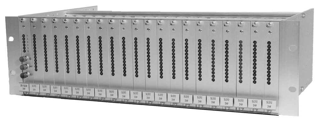
UNI - CONTROL - Series
annunciators in eurocard format for universal use
System features:
- Compact design using eurocard format
100 x 160mm / 4M installation wide - Installation of max. 246 signal lines in a
19" rack 84M / 3U - LED display per signal line
- Current type, polarity and phase control by any input stages with isolation relays
- Acknowledgeable automatic potential-free horn New-message,
with optional automatic shut-off horn
- Adjustable pick-up ordrop-out delay
- Multi-function circuit: closed-circuit /operating current changeover, first-up / new-value changeover
- Output isolation of power relay contacts 240V, 3A for lamp output
- Additional potential-free relay output max.125V, 1A
- Potential-free group message output with system monitoring
- EMC-values: UNITRO-Standard in accordance with EN 61000
ZR/RS3 master card with 3 signal lines,
RS6 alarm card with 6 signal lines (fig.3)
- Replaced by:
ZX3V master card with 3 signal lines,
RX6V signal card with 6 signal lines
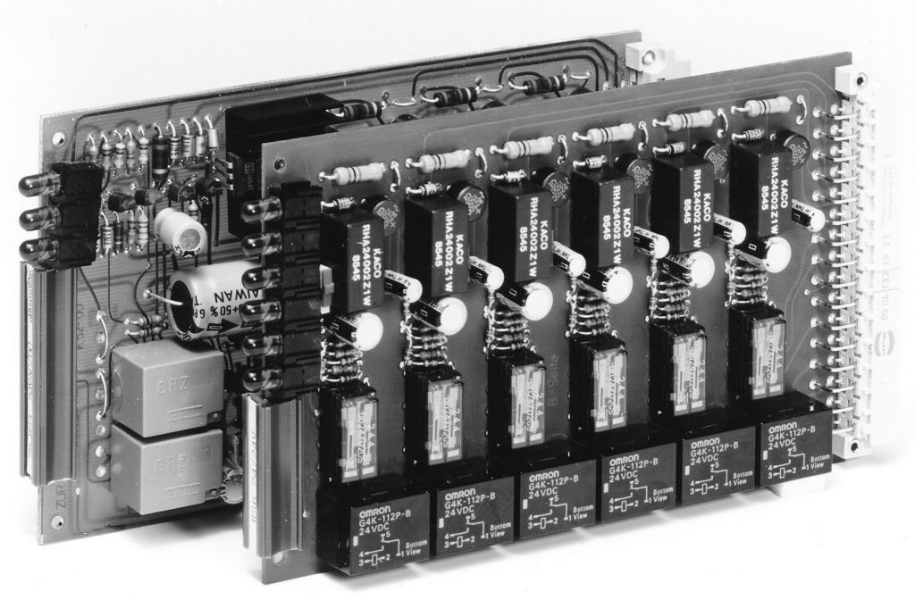
fig. 3
ZR1/SLS6 master card with 6 signal lines,
SLS12 signal card with 12 signal lines (fig. 4)
- alarm card with single flashing-light display with reset button
according to ISA-18.1 Seq. A / DIN 19235 4.1.2.1 or 4.1.3.1 - changeover from final to start-up value signal
- master card with flashing-light and horn reset button as well as lamp check button located on front panel
- front-panel LED display for each signal line
- one potential-free relay output for each signal line for lamp control
- closed-circuit/operating current changeover for each card
- see circuit diagram 51 for wiring layout (Link)
- function flow chart
UNITRO Level 3 (Link)
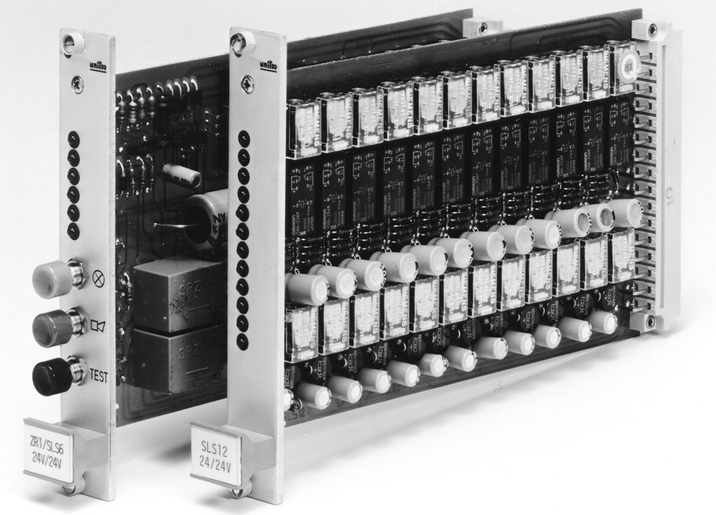
fig. 4
ZX3V master card with 3 signal lines,
RX6V signal card with 6 signal lines (fig. 5)
- alarm card with single flashing-light display with reset button
according to ISA-18.1 Seq. A / DIN 19235 4.1.2.1 or 4.1.3.1 - either manual or automatic acknowledgment by honking variable time step
- mode of operation as for the ZR1/SLS6 alarm combination and SLS12 alarm, but with the following technical additions:
- adjustable response delay for each signal line
- additional potential-free output (convertible make/break contact) for each signal line, can be coded for 3 functions
- output remains open until fault is reset (without voltage)
- output remains open until fault is cancelled and rectified
- output behaves like lamp output - closed-circuit/operating current changeover for each signal line
- see circuit diagram 52 for wiring layout (Link)
- function flow chart
UNITRO Level 3 (Link)
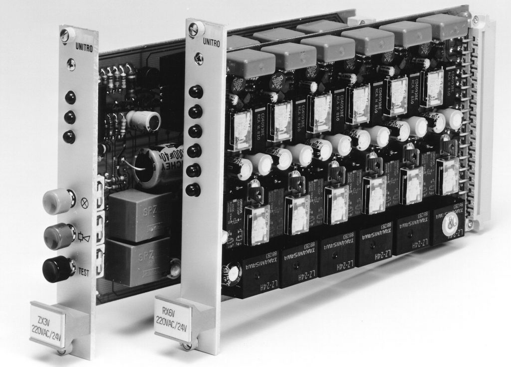
fig. 5
ZX2V/2 master card with 2 signal lines,
RX5V/2 signal card with 5 signal lines (fig. 6)
- alarm card with acknowledgeable double flashing light
according to ISA-18.1 Seq. R / DIN 19235 4.1.2.2 - mode of operation as for the ZX3V and RX6V alarm combination,
but with the following technical additions: - additional potential-free contacts per signal line as normally open contact with shared access
- each signal line can be assigned separately two acknowledgeable horn outputs
- alarm inputs, each with two separate connection points, that is absolute isolation
- see circuit diagram 53 for wiring layout (Link)
- function flow chart
UNITRO Level 5 (Link)
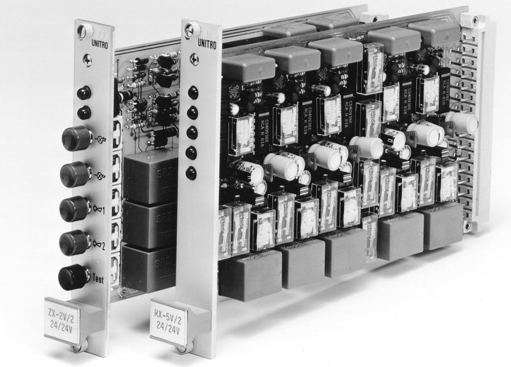
fig. 6
ZR1 / SLS4-BS master card with 4 signal lines,
SLS8-BS signal card with 8 signal lines (fig. 7)
- alarm card for combined operation messages and flashing fault messages with acknowledgeable new-value message
according to ISA-18.1 / DIN 19235 4.1.4.1 - either manual or automatic acknowledgment
- master card with flashing-light and horn reset button as well as lamp check button located on front panel
- front-panel LED display for each signal line
- one potential-free relay output for each signal line for lamp control
- closed-circuit/operating current changeover for each card
- function flow chart
UNITRO Level 4 (Link)
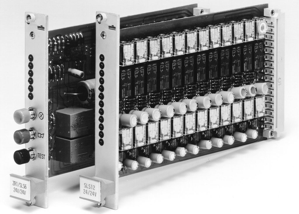
fig. 7
ZN3V master card signal lines,
SN4V signal card with 4 signal lines (fig. 8)
- alarm card with single flashing-light display with reset button
according to ISA-18.1 Seq. A / DIN 19235 4.1.2 or 4.1.3.1 - as an option to connect 2-wire NAMUR sensors
- mode of operation as for the ZX3V and RX6V, alarm combination,
but with the following technical additions: - short-circuit and wire break monitoring via separate LED display and common alarm
- red LED display for fault indication
- orange LED display for short-circuit and wire break monitoring
- see circuit diagram 55 for wiring layout (Link)
- function flow chart
UNITRO Level 3 (Link)
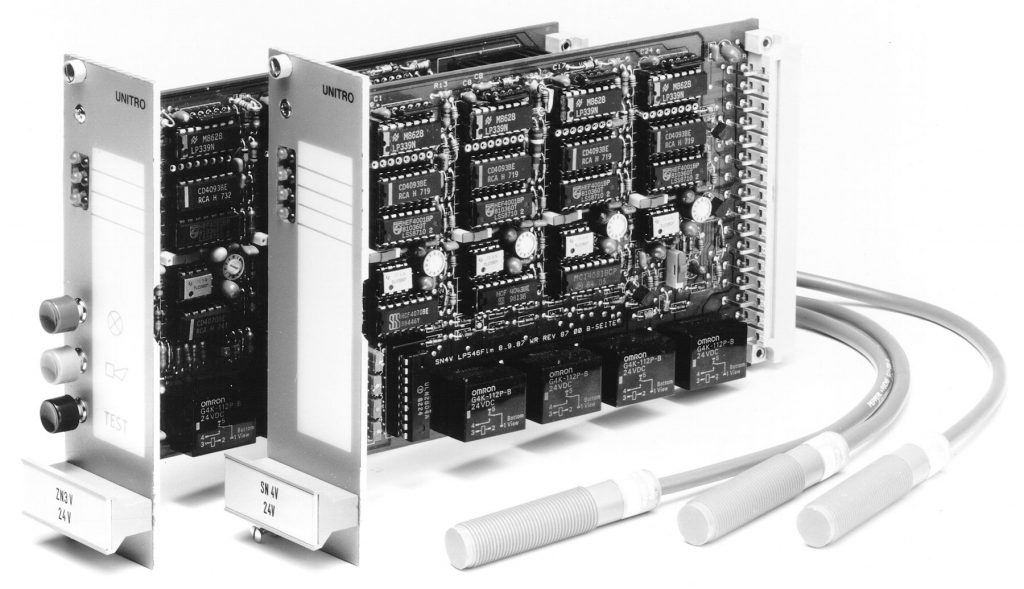
fig. 8
Mechanical characteristics
- Type of construction: plug-in cards in eurocard format 100 x 160mm, min. 4M installation wide
- Mounting position: required, preferably standing in the rack
- Connection: 32-pin male multiple connector according to DIN 41612, style D
- Leakage distances and clearances: in accordance with UNITRO-Standard
- Permissible relativehumidity: in accordance with UNITRO-Standard
- Permissible ambienttemperature: in accordance with UNITRO-Standard
- Weight for moduleincluding packaging: approx. 300g
Electrical characteristics
- Supply voltage: from the master card 24VAC ± 10%)
or 24V DC battery DC voltage DC supply (bus wiring) - External fuse: max. 4A
- Internal system voltage: 24V DC
- Internal fuse: on short-circuit protected voltage regulator
- Flashing frequencies: 2Hz, 0,5Hz• Outputs:
- potential-free acknowledgeable horn output: max. 220V AC, 3A
- potential-free group alarm output: max. 220V AC, 3A - Expandability: over power supply card to the base block 10 expansion modules
at external 24V DC power supply up to 50 expansion modules - Nominal voltage level for signals: 24V AC / DC to 230V AC / DC voltage adjusted
- Input trigger threshold: min. 80% nominal voltage
- Response delay: standard about 5ms (only 24V DC signal voltage possible)
with ZX or RX-type adjustable from 5ms to 10s (max 60s) - Minimum signal duration: 10ms
- Recovery timefor storage of individual messages and the horn output: max. 10s
- First value distinction: approx. 5ms
- Contact load
- lamp outputs: 250V / 3A
- additional relay outputs: min. 125V / 1A - Mechanical life of the output relay: 107 switching cycles
- Current consumption per signal input: input current 7-10mA external power supply
- Internal power loss per signal input:
RS6: 0,5VA
SLS12: 0,3VA
RX6: 0,75VA - EMC, immunity of interference: UNITRO-Standard,
in accordance with EN 61000 - Other system features: see data on the individual signal cards
System features:

