Page 7 - C3_series
P. 7

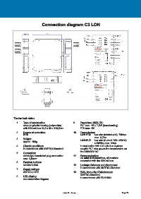
Connection diagram C3 LON


            Technical data:

               1.   Type of construction:                      9.   Power loss 100% ED:
                    snap-on plastic housing (polyamide)             PLT max. 1W / 7,5W (broadcasting)
                    with DIN-rail-bus 22,5 x 99 x 113,5mm           FTX max. 1W
               2.   Degree of protection:                      10.   Transmission:
                    IP20                                            LON FTX:    two wire (twisted-pair), 78kbps
                                                                                max. 2,7km
               3.   Weight:                                         LON-PLT:    two wire (C-band 125-145kHz)
                    approx. 150g
                                                                                4,8kBit/s, max. 30km
               4.   Climatic conditions:                            in conjunction with C3 LON-bus 3-phase
                    in accordance with UNITRO-Standard              coupler PLT also power line transmission on
                                                                    the 230/400V AC
               5.   Connection:
                    screw-type terminals/ plug connection      11.   Parameterization:
                    max. 2,5mm²                                     via mini USB-interface, all modules
                                                                    connected with the DIN-rail-bus
               6.   Function buttons:
                    service button                             12.   Leakage distances and clearances:
                                                                    in accordance with UNITRO-Standard
               7.   Supply voltage:
                    24V DC ± 10%                               13.   EMC, immunity of interference:
                                                                    UNITRO-Standard,
               8.   LED-display:                                    in accordance with EN 61000
                    see connection diagram


                                                      subject to change                                 Page 74
   2   3   4   5   6   7   8   9   10   11   12