
Page 9 - Central fault indicating_units
P. 9
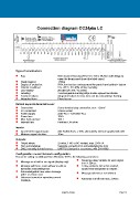
Connection diagram CC24 LC
Type of construction:
Bay: Wall-mounted housing (PS) 233 x 200 x 99,5mm with hinge to
open the front panel (insert the label strips)
Weight approx: 1.500g
Degree of protection: IP54, terminal box embossment for ports from behind + below
Climatic conditions: 5 to +55°C, 5 to 85% relative humidity
LED-display: 25 LED (24x red / 1x green)
Labelling: 3 exchangeable marking strips double spaced inscribable
Function buttons: integrated buttons for test, horn and 2x acknowledge flashing
Integrated horn: Piezo buzzer
Behind separate terminal cover:
Connection: Screw terminal plug connection, max. 1,5mm²
PC connection: USB-B socket
Power supply: 230V AC (= 120-250V AC)
Power loss: 15VA
Max. back-up fuse: 10A L
Internal fuse: Picofuse 1,6A slow
Inputs:
Input level for signal inputs: 24V AC/DC 8mA, ± 15%, alternatively internal supplied with 24V
Minimum signal duration: 10ms
Outputs:
Output relays: 2x relay, 1 NO or NC contact, max. 250V 5A
Horn acknowledge: Separate connection for acknowledging the horn
EMC, immunity to interference: UNITRO-Standard in accordance with EN 61000
Configuration menu / Network configuration:
Parameter setting via USB port from Windows 10 Pro, the following parameters:
Response delay variable for each signal
Message as a fault or run signal (display only)
from 1-254sec
Message with horn, -horn without or with an 2 relay contacts, NO or NC contact,
automatic acknowledgment inputs freely assignable to outputs
Acknowledgeable new value message
with 1 or 2 flash rates Message relevant or not relevant
Quiescent current or operating current
message Automatic cut-off horn max. 254sec
subject to change Page 116