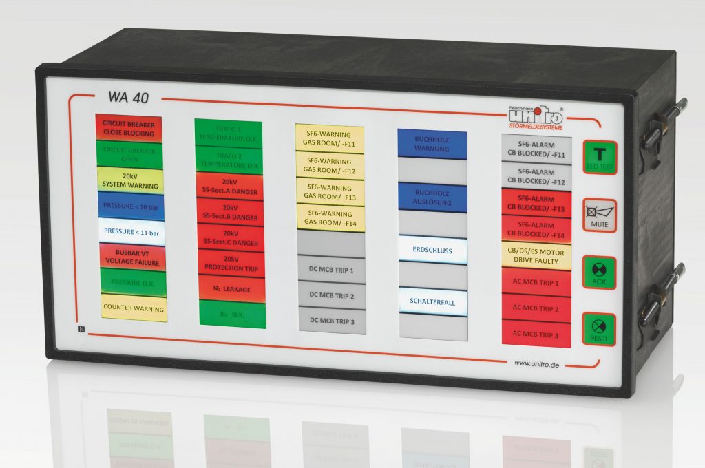
WA 40 (M) + WA 40-S
Control board mounting annunciator system
Controls and displays
- Bright 12,5 x 32mm RGB light field displays
- Easily exchangeable label strips
- Integrated mini horn and 4 RGB backlit function buttons (only WA 40 (M))
- Integrated web-page to display the luminous fields (in the color of the display),
the message texts and group messages, as well as acknowledgment of the messages - E-mail remote alarming (SMTP)
Parameterization
- Integrated Mini USB and NFC interface for parameterization using Windows 7 Pro or higher
- Acknowledgeable new alert/first alert flash warning, all sequences ISA-18.1-1979 (R2004) and DIN 19235
- New alert / first alert, Quiescent / operating current – for each signal
- Inputs freely assignable to outputs for each signal
- Response delay variable for each signal from 50ms to 10min
(in steps of 50ms, 2s and 1min) - History with ring memory for 8000 messages
- Light field displays: selectable colors (red/green/yellow/blue or white)
Electrical characteristics
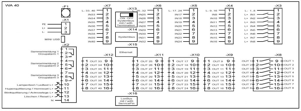
- 40 signal inputs, common ground (per 8-block) max. 230V AC / 240V DC with filter switching and electrical isolation
- Resolution and switching precision ≥ 10ms
- EMC-values: Higher immunity levels to UNITRO-PSC-Standard
- Potential-free outputs: normally open relay max. 2A 250V AC, 0,3A 220V
- 3x group signal outputs: changeover relay max. 2A 250V AC, 0,3A 220V DC (only WA 40 (M))
- States saved to memory on power failure
Mechanical characteristics
- Plastic junction housing (288 x 144 x 120 + 25mm)
- Connection: Screw-type terminals, plug connection max. 2.5mm²
Options
- Expandable to max. 200 signal inputs by max. 4 expansion modules WA 40-S
- LON bus interface or Ethernet interface or (TCP/IP with IEC 61850 or IEC 60870-5-104 protocol currently not available)
Technical data:
- Type of construction:
control board housing 288 x 144 x 120 + 25mm
(cutting for installation 282 x 138 + 1mm)
- Degree of protection:
front: IP50
housing: IP20
- Weight:
WA 40 (M) max. 2600g
- Climatic conditions:
in accordance with UNITRO-PSC-Standard
- Connection:
screw-type terminal/ plug-in connection max. 2.5mm²
- Supply voltage:
24V AC/DC or
48-60V AC/DC or
110V AC/125V DC or
230V AC/240V DC
voltage-adapted
- Alarm signal nominal voltage:
24V AC/DC or
48-60V DC or
110/125V DC or
220/240V DC or
230V AC
voltage-adapted,
voltage tolerance ±10%
- Input level for signal inputs:
at 24V AC / DC 8mA
at 230V AC 7mA
at 60V DC 4mA
at 110 / 125V DC 3mA
at 240V DC 2mA
- Data retention in the absence of power:
20 years
- Resolution:
≥ 10ms (relay)
- Switch-on delay:
programmable from 50ms to 10min
(in steps of 50ms, 2s and 1min)
- Minimum signal duration:
10ms
- First-up discrimination:
10ms
- Flashing frequencies:
2Hz / 0.5Hz
- Power loss:
max. 20W
- Relay outputs:
max. 2A 250V AC,
0,3A 220V DConly WA 40-M:
3x group signal outputs, changeover,
max. 2A 250V AC,
0,3A 220V
- Parameterization interfaces:
Mini USB and NFC interface for parameterization
- Leakage distances and clearances:
in accordance with UNITRO-PSC-Standard
- EMC, immunity to interference:
UNITRO-PSC-Standard, immunity higher
degrees of severity according to the
actual generic standards DIN EN 61000
subject to change


