Page 13 - C3_series
P. 13

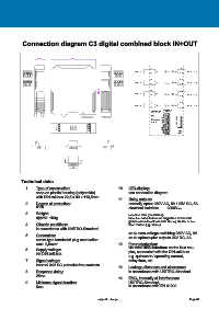
Connection diagram C3 digital combined block IN+OUT


                     2 2 . 5            9 9

                                                                                   1                9
                                                                          I N   1     1     A   5     O U T   1
              9  10 11 12                                          1   2   3 4     2              1 0
                                                                                   3              1 1
              13 14 15 16                                          5   6   7 8
                                                                          I N   2     2     B   6     O U T   2
                                                                                   4              1 2
                                                       3 . 5                       5              1 3
                                                       1 1                I N   3     3     C   7     O U T   3
                                                                                   6              1 4
                                                                                   7              1 5
                                                                          I N   4     4     D   8     O U T   4
                                                                                   8              1 6
                                                                                   D i p -S w i tc h  8  D ip - S w itc h
                                                                                   - T e rm i n a t i o n  4  3  2  1
                                                                                           1
                                                                                           2
                                                                                   LE D
                                                                                     A     4    8 7
                                                                                     B     5    6
                                                                                   C  i n t.  B U S    6  5
                                                                                   D   P o we r  A d d re s s I n p ut M o d ul   3   7   8  4
                                8  4              16                                       9    3 2
                                7    3    A  B  C D  9   10   11   12  15                1 0 11  1
                                6  2   1 2   3  4  5 6   7   8  14                       1 2 1 3  ON OFF
                                5    1            1 3                                    1 4     O N
                                                                                         1 5     O F F
                                                                                         1 6


            Technical data:
               1.   Type of construction:                        10.   LED-display:
                    snap-on plastic housing (polyamide)                see connection diagram
                    with DIN-rail-bus 22,5 x 99 x 113,5mm
                                                                 11.   Relay outputs:
               2.   Degree of protection:                              normally open: 250V AC, 5A / 25V DC, 5A
                    IP20                                               electrical isolation:   2000Vrms

               3.   Weight:                                            inductive load (contactors):
                    approx. 150g                                       mount-in anti-interference capacitors at the coils,
                                                                       please use external interlock, driving shutter or sun
               4.   Climatic conditions:                               blind motors (up / down)!
                    in accordance with UNITRO-Standard
                                                                       or 4x zero-voltage switching 250V AC, 2A
               5.   Connection:                                        or 4x optocoupler outputs 24V DC, 2A
                    screw-type terminals/ plug connection
                    max. 2,5mm²                                  12.   Parameterization:
                                                                       via mini USB-interface on the Bus cou-
               6.   Supply voltage:                                    pler, connected with the DIN-rail-bus:
                    via DIN-rail-bus
                                                                       e.g. quiescent / operating current,
               7.   Signal voltage:                                    delay time, etc.
                    internal 24V DC potential-free contacts
                                                                 13.   Leakage distances and clearances:
               8.   Response delay:                                    in accordance with UNITRO-Standard
                    25ms
                                                                 14.   EMC, immunity of interference:
               9.   Minimum signal duration:                           UNITRO-Standard,
                    5ms                                                in accordance with EN 61000


                                                      subject to change                                 Page 80
   8   9   10   11   12   13   14   15   16   17   18